wddrive-studio
Overview
wddrive-studio is the unified WD DRIVE host application. It brings two jobs into one interface:
- Drive control: act as a CANopen / CiA-402 master — browse the object dictionary, switch operating modes, capture live waveforms, configure RPDO / TPDO, and sequence motion with blocks.
- Device maintenance: discover the drives on the bus, update firmware, and set CAN ID, baudrate and controller protocol.
It works together with a CANopen master gateway: the PC connects to the gateway over a USB virtual serial port (USB VCP), and the gateway connects to the drives on the CAN bus. Windows, macOS and Linux are all supported.
The installer also bundles the wdd-maintain-cli command-line maintenance tool, which performs the same device maintenance and bulk firmware updates in headless environments — see the wddrive-maintain-cli guide.
This guide covers day-to-day use: installation and connection, every drive-control view, blocks, device maintenance, and settings and updates. If you just want to see the motor move for the first time, start with Quick Start.
Install and Launch
- Open the downloads page, download the wddrive-studio installer for your operating system and install it.
- Launch the app. The full interface appears on first launch: top bar, feature tabs, and a status bar at the bottom.
The app checks for updates automatically on startup (this can be turned off in Settings). See “Settings and Updates” below for how a new version is handled.
Connect a Device and Select a Node
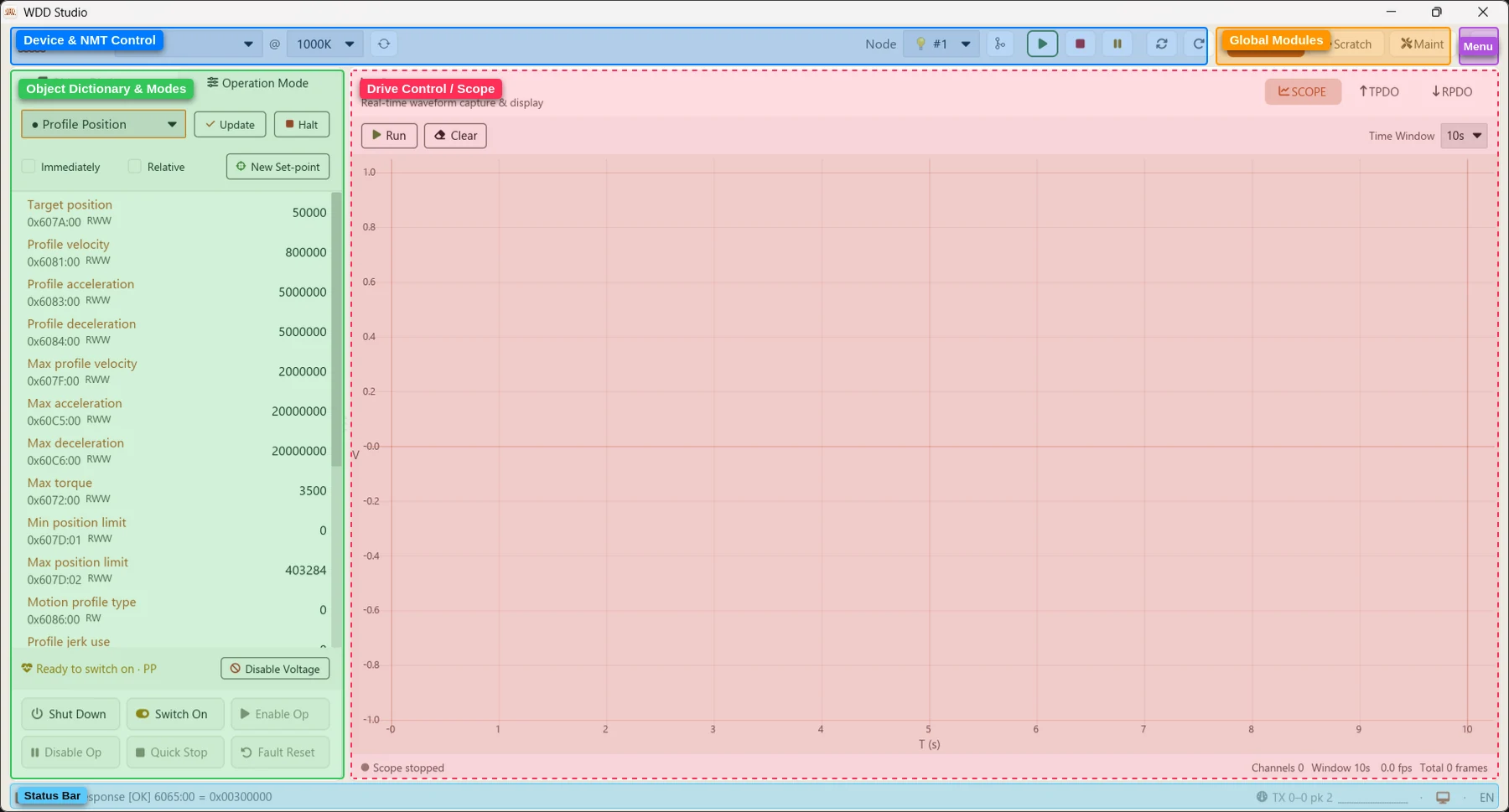
- Pick the WD DRIVE USB-CAN gateway in the Device dropdown at the top. Selecting it connects automatically; the first item, “Close Device”, disconnects.
- If you unplugged the adapter, click the Refresh button next to it to re-enumerate serial devices.
- Once connected, set the Baud rate. The default is 1000K (= 1 Mbit/s), matching the drive’s factory default. The value is written to the gateway and triggers a CANopen reset so the bus restarts at the new rate; if you change it before connecting, it is sent automatically on connect.
- Choose the target motor in the Node dropdown. Online nodes carry a 💡 icon and are listed first. The factory default node is 1.
If the Device dropdown is empty, click refresh first; if it stays empty, check the USB cable, adapter power and driver. If the Node dropdown shows no online node, it is usually a baudrate mismatch, reversed CAN_H/L, missing 120 Ω termination, or the drive being unpowered.
After selecting a node, the NMT control buttons at the top-right apply to it: Start, Stop, Pre-Op, Reset Comm and Reset Node. A button stays outlined to show the node’s current NMT state at a glance. Note that NMT Stop disables SDO — watch the status bar.

LSS Node ID Configuration (CiA 305)
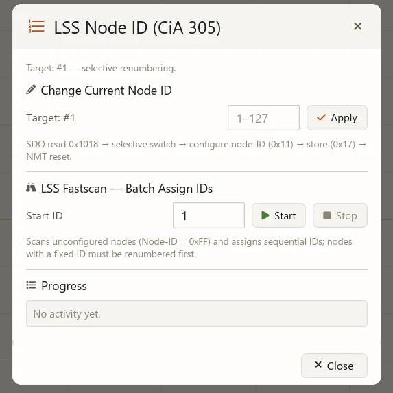
Click the LSS button in the top bar to open the node-ID configuration dialog. Depending on whether a target node is selected, it offers different methods:
- Change Current Node ID (a target node is selected): enter a new ID from 1–127 and click “Apply”. The sequence reads the
0x1018identity → selective switch → configure node-ID (0x11) → store (0x17) → NMT reset. - Global Switch — Broadcast Renumber (no target node selected): broadcasts the new ID to all nodes on the bus. Only use this when a single device is on the bus, otherwise IDs will collide.
- LSS Fastscan — Batch Assign IDs: scans unconfigured nodes (Node-ID = 0xFF) starting from the given “Start ID” and assigns sequential IDs. Nodes with a fixed ID must be renumbered first before Fastscan can find them.
The “Progress” area at the bottom of the dialog shows the operation log in real time.
LSS operations send an NMT reset, so the node restarts briefly. Make sure the bus is wired correctly and the baudrate matches, and avoid changing the ID of a node that is currently in use.
Interface Overview
The global tabs in the middle of the top bar split the app into three areas:
- Control: CANopen / CiA-402 debugging, with content sub-tabs SCOPE, TPDO and RPDO.
- Scratch: block-based motion programming.
- Maintenance: device discovery and firmware updates.
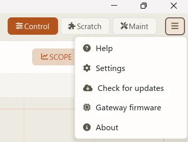
The hamburger menu at the top-right contains Help, Settings, Check for updates, Gateway firmware and About.
The status bar at the bottom shows the current state (ready, node count, operation hints) plus runtime information such as the gateway TX watermark.
Object Dictionary (SDO)
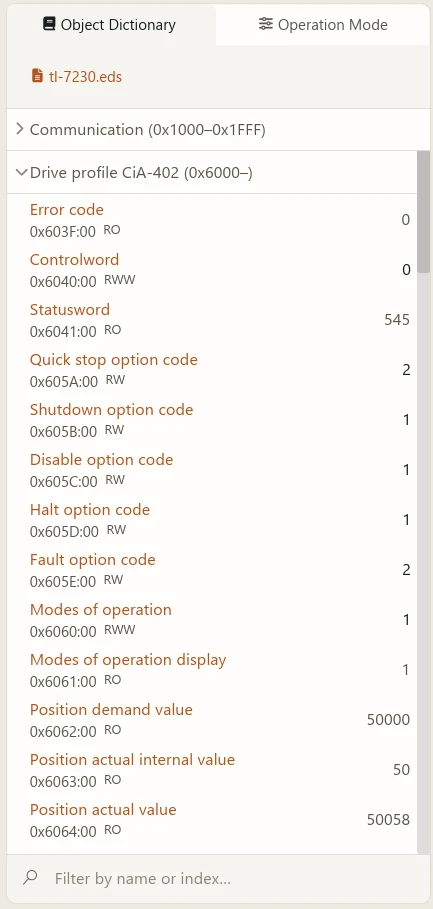
The object dictionary (OD) sidebar on the left of the Control view reads and writes device parameters over SDO. For the full object dictionary (index/sub-index, data type, access, PDO mapping and persistence) see the object dictionary reference.
- EDS selection: the dropdown at the top lists built-in and user EDS files; selecting one displays its object dictionary. After you select a node, the app reads the node identity (
0x1018) and matches the product EDS automatically; when there is no match it falls back to generic CiA-402. - Filter: type a name or index in “Filter by name or index…” to find objects quickly.
- Read / write: expand an object and click the object name to read its current value; enter a value in the input box and press Enter to write it. Write acknowledgements and read results appear in the transfer log.
- The CiA-402 Controlword panel provides quick “Halt” and “Resume” actions.
When a node is in NMT STOP, SDO is disabled and the status bar says “SDO disabled (CiA-301)”. Use Start in the top bar to bring the node back to a communicable state.
Operating Modes and Controlword
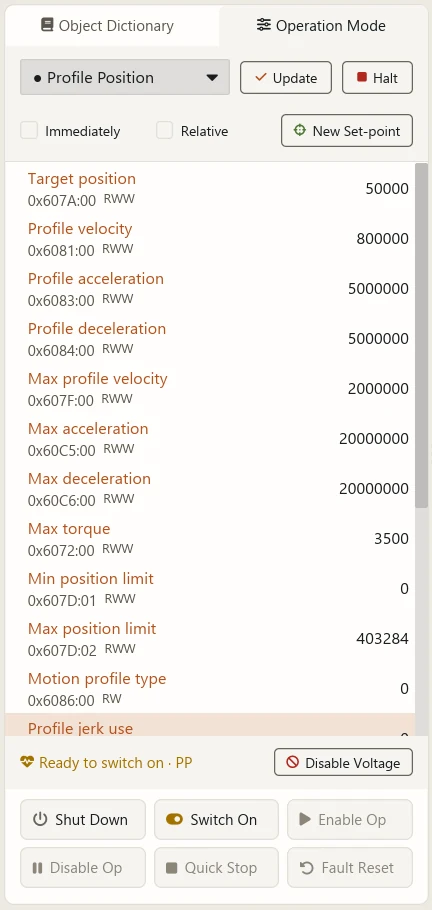
The Operation Mode selector at the top of the sidebar switches the CiA-402 operating mode:
- No Mode / Profile Position (PP) / Velocity (VL) / Profile Velocity (PV) / Profile Torque (PT) / Homing (HM) / Interpolated Position (IP) / Cyclic Sync Position (CSP) / Cyclic Sync Velocity (CSV) / Cyclic Sync Torque (CST).
- After selecting, click “Update” to write it and read back
0x6061(Modes of operation display) for confirmation. A “●” before an option marks the mode currently active on the device. - The common parameters panel below the selector reads and writes objects related to the mode; if there are none it says “No common settings for this mode”.
- The app reads
0x6502(Supported drive modes) and only offers modes the device supports.
If the device does not accept the requested mode, the status bar says “Mode not accepted by the device” and shows the mode actually read back. Check that the mode is supported and that its preconditions are met.
Scope (SCOPE)
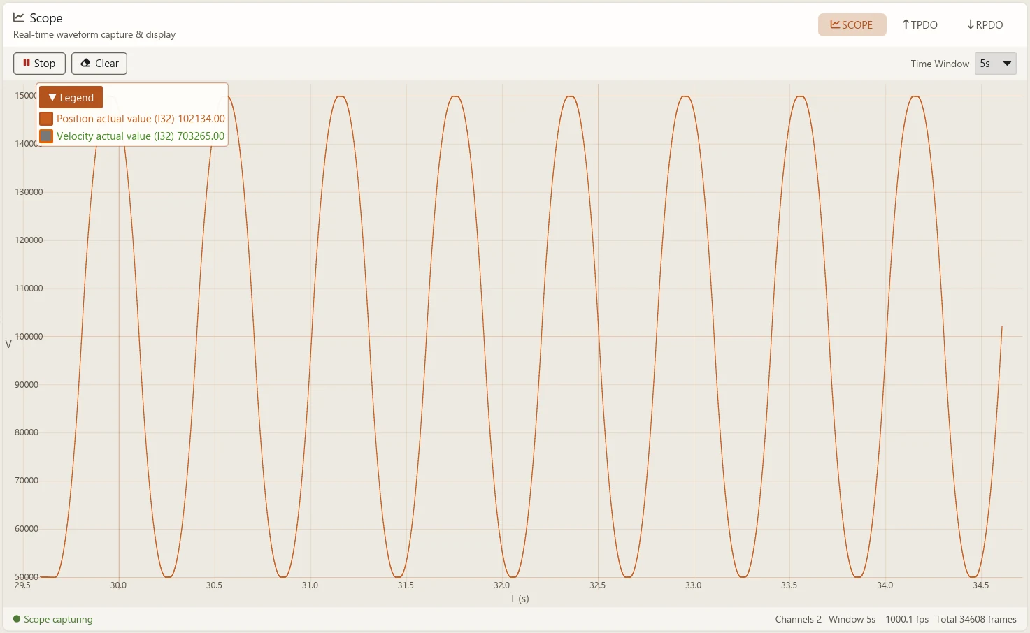
The SCOPE sub-tab of Control displays waveforms reported over TPDO in real time.
- Pick the objects to observe (position, velocity, torque, etc.) from the channel list; the app maps them to TPDO and captures them.
- The “Run / Stop” button controls the scrolling waveform; “Clear” empties the captured data.
- The Time Window selects 5 / 10 / 20 / 30 seconds for the horizontal axis. After stopping you can drag and zoom to review the frozen curves.
- The info bar at the bottom shows channel count, window, frame rate and total frames.
Scope channels come from the TPDO mapping. If the waveform is empty, first check that the node is NMT Operational and that the relevant TPDO is configured.
RPDO and TPDO
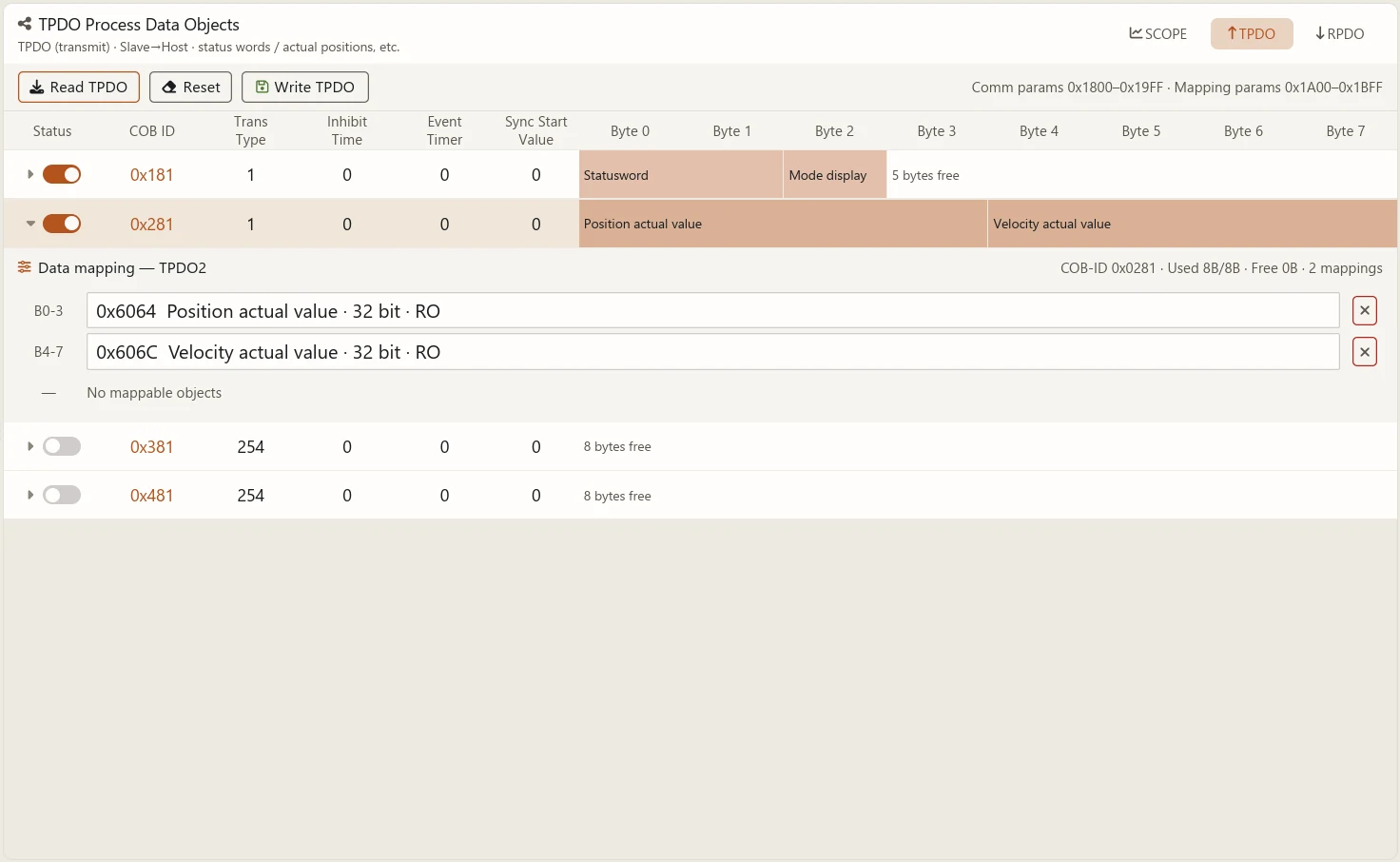
Process Data Objects (PDO) exchange realtime data periodically:
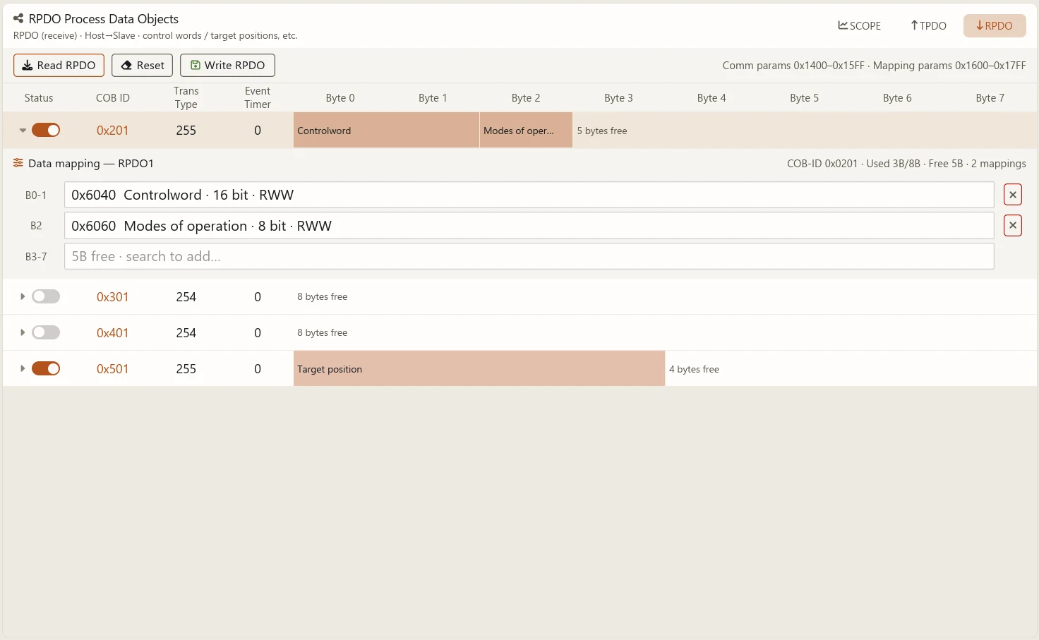
- RPDO (receive): host → slave, for control data such as controlword and target position.
- TPDO (transmit): slave → host, for monitored data such as statusword and actual position.
Both sub-tabs work the same way:
- Click “Read RPDO / TPDO” to read the current communication parameters and mapping from the device; the table refreshes.
- Edit the table: communication parameters (COB-ID, transmission type, enable, etc.) and mapping entries. The mapping editor supports search to add or search to replace by object, and shows each frame’s COB-ID, used/free bytes and mapping count live.
- Click “Write RPDO / TPDO” to write the edited configuration back over SDO, one entry at a time. Progress is shown, and the status bar reports the number of writes on completion.
- “Reset” returns the table to its initial state so you can start over.
PDO are only processed by the slave when the node is in NMT Operational. In Pre-Op or Stopped, PDO writes have no effect and the status bar says “not NMT Operational — RPDO write is ignored”. Use Start in the top bar first.
Scratch
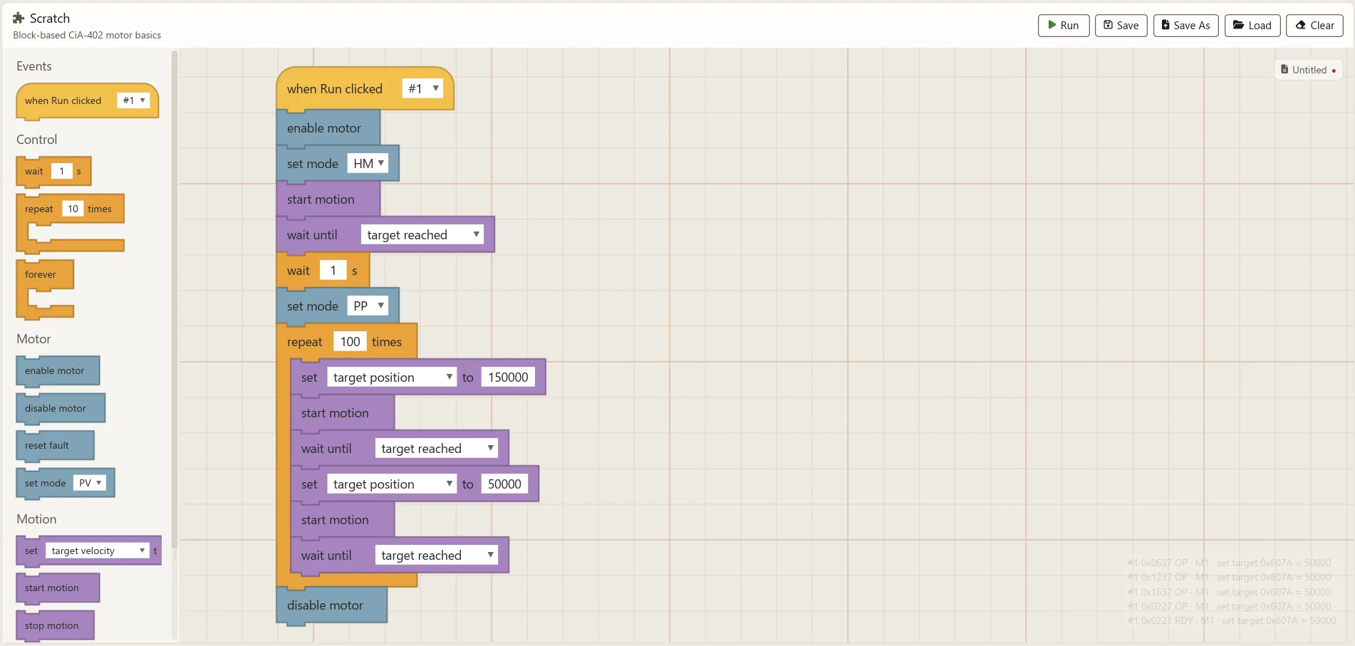
The Scratch tab is a block-based motion-programming canvas. Drag blocks together to sequence CiA-402 actions — ideal for basic tests and demos.
- The block library is grouped into Events, Control, Motor, Motion and Sensing. Common blocks include “when Run clicked”, “enable motor / disable motor”, “set mode”, “set target”, “start motion / stop motion”, “wait”, “repeat”, “forever” and “read statusword”.
- Drag blocks from the library and snap them into a script. The canvas already has the built-in example loaded, so you can run it right away.
- Click “Run” (the green flag) at the top to start; press “Stop” at any time.
- The toolbar offers “Save / Save As / Load / Clear” for script files; “Save” writes back to the current file, and the first save opens “Save As”.
- Before running, the app performs checks and reports possible problems in the status area (no “when Run clicked” script, starting motion without a mode, node offline, read-only target object, and so on).
- The monitor bar at the bottom-right of the canvas shows the bound node’s state and feedback in real time.
Blocks are sent to the real device over SDO / RPDO. Before running, make sure the mechanism has safe travel and software limits, and that the node number bound to the blocks matches the actual device.
Device Maintenance (MAINT)
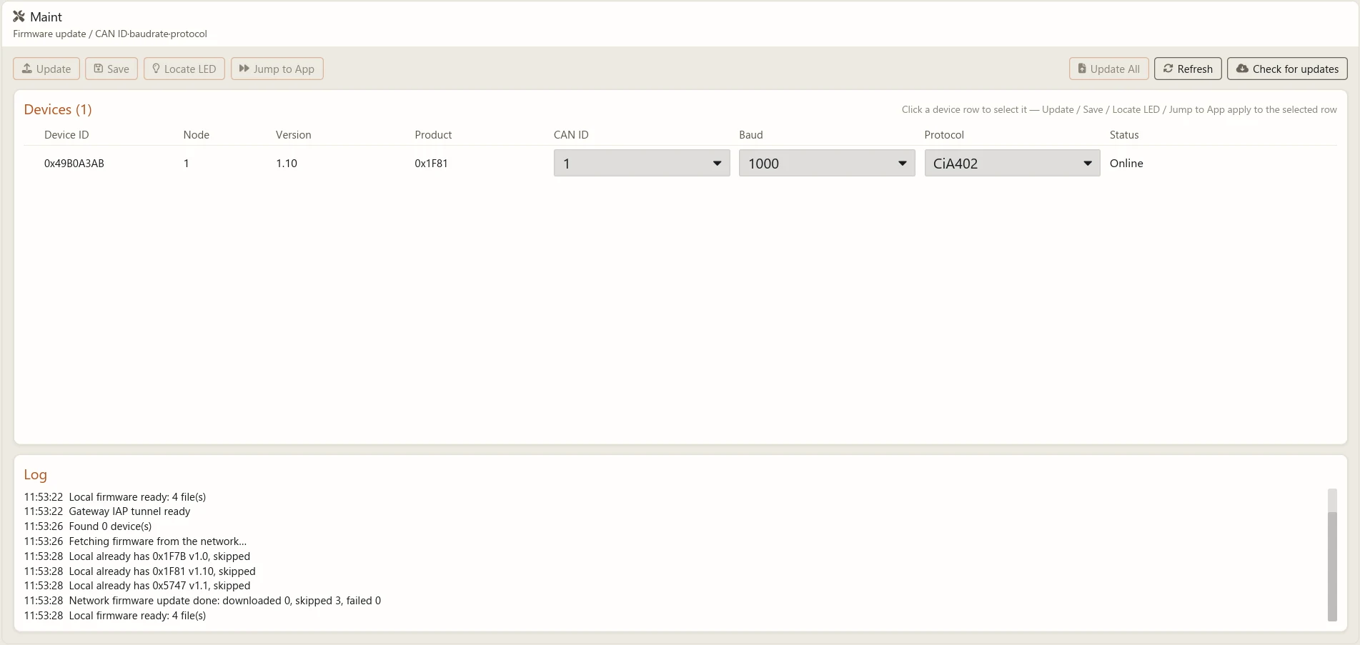
The Maintenance tab discovers devices, updates firmware and sets device parameters. Entering the tab automatically establishes an IAP tunnel through the gateway serial port and releases it when you leave, so normal drive control is unaffected.
Connect the gateway serial device in the top bar first. If the gateway firmware is too old to support the IAP tunnel, the page asks you to upgrade it and disables maintenance.
The device list shows the devices on the bus that are in update mode, with columns Device ID, Node, Version, Product, CAN ID, Baud, Protocol and Status.
- Per-device actions: Update (upgrade to the matching firmware), Config (change CAN ID / baudrate / protocol, then “Save” to apply), Jump to App (leave IAP and boot the application) and Locate LED (blink an indicator so you can identify the device on a rack).
- Above the list are “Update All” and “Refresh”.
To bring a device into update mode, reset or power-cycle it. Never power off or disconnect during a firmware update.
Settings and Updates
Open the Settings dialog from the hamburger menu. Interface language, theme, SYNC period and similar choices are stored in a local configuration file and restored on the next launch.
Language and theme
- Language: switch the interface language (简体中文 / English) and it takes effect immediately.
- Theme: Light / Dark / Follow System.
SYNC period
Set the gateway SYNC frame period with presets of 1 / 2 / 5 / 10 ms. A shorter period reports synchronous TPDO more densely and gives finer waveforms, but raises bus load; the signal generator’s control rate scales proportionally (gateway resolution is 1 ms).
Software self-update
- Use “Check for updates” in the hamburger menu for a manual check; the app also checks once on startup according to settings.
- When a new version is found, choose “Download & update” or “Skip this version”.
- Once downloaded and unpacked, click “Restart now” so a helper replaces the files in place and restarts. System-package installs (such as a Linux
.deb) instead ask you to update with your package manager.
Gateway firmware update
Open “Gateway firmware” from the hamburger menu:
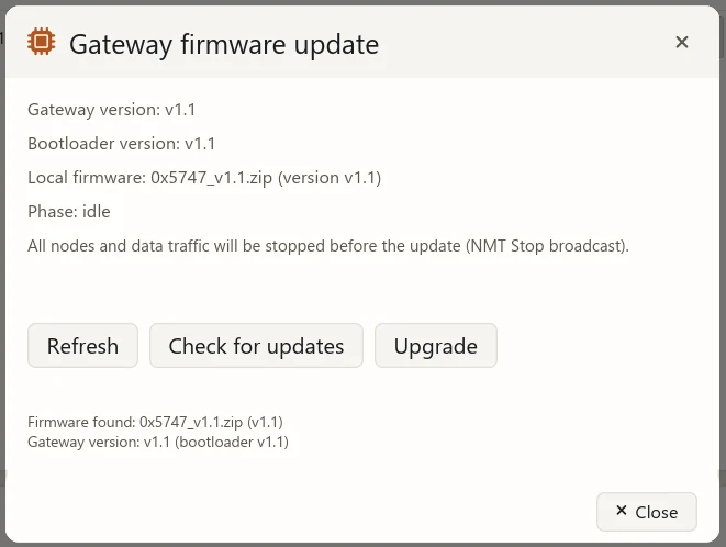
- The dialog shows the gateway’s current version, its bootloader version, and the firmware downloaded locally.
- If no firmware is present yet, click “Check for updates” to download it from the network.
- Click “Upgrade”. Before the update, the app broadcasts NMT Stop (node 0) to stop all nodes and data traffic; the gateway then enters update mode, writes the image, restarts and verifies the new version.
- Each phase (probing the gateway, entering update mode, writing, booting, verifying) is shown live.
Do not power off or disconnect USB during the update. If the gateway firmware is too old, it may ask you to flash a newer version once with a debugger.
About
“About” in the hamburger menu shows the app version and feature list (NMT, SDO, PDO, scope, and so on).
FAQ
| Symptom | Likely cause | Fix |
|---|---|---|
| Device dropdown is empty | Gateway not enumerated | Click refresh; check the USB cable, adapter power and driver. |
| Node dropdown shows no online node | Bus communication failure | Confirm the baudrate matches, CAN_H/L are not crossed, there is 120 Ω at each end, the drive is powered, and the node ID is correct. |
| Status bar says “SDO disabled (CiA-301)” | Node is in NMT STOP | Send NMT Start with Start in the top bar, then retry. |
| RPDO writes have no effect | Node is not NMT Operational | Bring the node to Operational first (Start in the top bar). |
| Mode does not take effect after writing | Device does not support it, or preconditions not met | Check the 0x6502 support list and the statusword; look for “Mode not accepted by the device” in the status bar. |
| EDS does not match after switching nodes | 0x1018 identity does not match any bundled EDS |
Pick the correct EDS manually in the dropdown, or place the matching EDS in the user EDS directory. |
| Maintenance says the IAP tunnel is unsupported | Gateway firmware is too old | Upgrade the gateway firmware to a build supporting the IAP tunnel, then reconnect. |
| Firmware update interrupted | USB disconnected or power lost | Reconnect and retry; always keep power and connection during an update. |
Next Steps
- Wiring, connecting and first motion: Quick Start
- The standard CiA-402 state machine and operating modes: CiA402
- Using WD DRIVE motors under Klipper: Klipper
- Command-line maintenance in headless environments: wddrive-maintain-cli